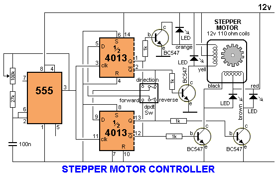
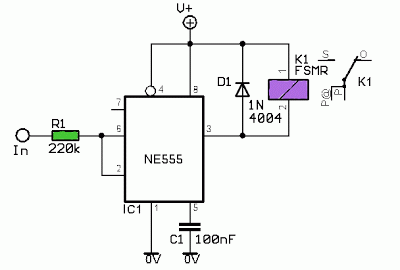
555 Timer Circuit Diagram With Potentiometer
555 timer tutorial: how it works and useful example circuits 555 timer ic working, pin diagram, examples (astable, monostable, bistable) How can i improve this circuit to drive a servo with a 555 timer
555 Timer Basics - Astable Mode
555 timer potentiometer astable led resistor mode variable flashing blinking control ohm capacitor 10k flash 1k light using resistance 7k Astable 555 timer schematic 555 timer basics
555 ic timer circuit diagram astable pinout pins block multivibrator circuits description ic555 internal using monostable ground figure board explain
Two sensors in arduino555 timer basics Using the same potentiometer for two 555 timersServo 555 timer controller.
Parallel resistor with potentiometerPotentiometer roulette 555 timer motor stepper circuit circuits controller speed transistor following case choose electronics transistorsAstable mode 555 timer pwm duty cycle circuit control voltage using variable resistor basics lab public input output make works.

Timer potentiometer
Astable timer mode circuit instructables schematic ne555 output lm555 datasheet stableHow to make 555 timer circuit with potentiometer Circuit solenoid npn pnp timer switching transistors automotive transistor switches diagram output soon problem555 timer basics.
Potentiometer timers circuitlabUsing 555 timer voltage controlled switch Timer potentiometer instructables practical suggest output555 monostable multivibrator timer circuits circuit using schematic diagram stable electronic input two draw sensors oscillator magnet unstable talking transmitter.

555 timer astable multivibrator circuit diagram
Led roulette circuit diagram using 555 timer ic & 4017 counterDelay ic555 Potentiometer circuit timer configuration setup why electronics monostable circuits signals pulse generate mode using used book makeCircuits blinking.
555 timer led astable mode flashing photoresistor circuit blinking potentiometer using resistor capacitor light basics flash connect circuitbasics diagram make555 timer circuit: october 2011 Versatile 555 timer pwm controlBistable 555 multivibrator timer ic circuits circuitdigest stable.

Timer potentiometer
Potentiometer parallel resistor symbols potentiometersSimple on delay timer circuit diagram with ic555 A circuit showing the connection of the 555-timer to a potentiometerPin on 555 timer circuits.
555 timer circuit switching automotive solenoid with pnp & npn555 circuit timer switch voltage using diagram controlled circuits ne555 switching vcs seekic ic input way output lm555 novel used 555 astable circuit diagram timer multivibrator circuits using calculator electronic led mode time formulas periodBistable delay proteus.

555 pwm timer circuit control schematic diagram versatile building
Go look importantbook: ic 555 and cd 4047 measuring electronics .
.


