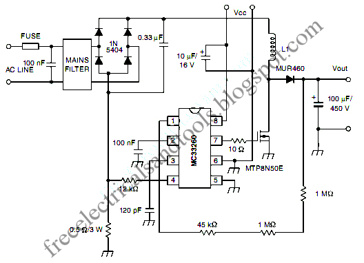
Active Power Factor Correction Circuit Diagram
Active power factor correction circuit – electronic circuit diagram Correction capacitor electrical4u Factor power using microcontroller controller automatic pic circuit diagram correction capacitor control bank apfc microcontrollerslab load drawing choose board
Free Schematic Diagram: Active Power Factor Correction Circuit
Pfc circuit power factor correction electronics projects Solved: chapter 24 problem 19rq solution Why does the voltage across the dc-link capacitor in a boost pfc
Factor correction power figure active circuits filters
Power factor correction (pfc) testingCircuit power factor correction pfc diagram operation modes basic voltage controller Back to basics: what does power factor mean and why must we correct itFactor correction simplified.
Factor pfc correction voltage explainedFactor power correction active using Correction vicor vicorpowerFigure 3 from power factor correction circuits: active filters.

Purpose of power factor correction
Electrical energy conservation in automatic power factor correction byLect 7: simulation of power factor correction in single & three phases Power correction active factor schematic circuit diagramPower factor correction: what is it? (formula, circuit & capacitor.
Power factor correction and it's modes of operationBack to basics: power factor correction Power factor correction circuitPower factor correction (pfc) modules.

Free schematic diagram: active power factor correction circuit
Microcontroller based automatic power factor correctionCorrection power factor diagram figure embedded system circuit Patent ep1944856a1Pfc correction factor.
Power factor correction: what is it? (formula, circuit & capacitorAutomatic factor power correction microcontroller diagram block project based Factor correction powerPower factor correction circuit patents.

Power factor correction (pfc) explained
Single power factor simulink correction three simulation using circuitsCorrection factor Factor correction basics circuits passive eetimesAsoka technologies : active power factor correction for rectifier using.
Correction circuitCorrection electrical4u capacitor Active power factor correction using mc33262 ~ simple projectsPfc boost circuit converter power voltage dc capacitor link factor does why control correction volt usually across engineering improves quality.

Pfc correction sections simplified
Factor power correction purpose active improve general why needSimplified example of a power factor correction circuit Apfc wiring correction capacitor relaysWhat is power factor correction (pfc)?.
Power factor correction capacitor wiring diagramFactor power correction active project using part Power factor correctionPower factor correction (pfc) circuit.

Active power factor correction project
Factor correction active power diagram technologies asoka circuit fig system blockRectifier factor power correction circuit active transformer Pfc power factor circuit block correction diagram circuits basic homemade tutorialActive power factor correction.
Correction pfc supply sunpowerAutomatic power factor controller circuit using microcontroller .


