Astable Circuit Diagram 555 Timer
555 timer ic: internal structure, working, pin diagram and description Astable circuitbasics Astable 555 circuit ic multivibrator timer using pulse generator diagram light help sensor circuits audio make connect pc chip identifying
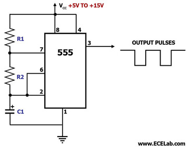
555 Timer as an Astable Multivibrator - Electronic Circuits and Diagram
555 astable circuit oscillator timer arduino frequency ic pwm 40khz multivibrator wave square pulse signal electronic circuits halve capacitor mode Astable multivibrator using 555-timer proteus simulation Ready to help: astable multivibrator using ic 555
Simple astable 555 timer ic flasher
555 astable timer multivibrator ic using ne circuit diagram circuits output counter led electronics op working555 timer astable circuit and equations 555 timer ic applicationsCircuit astable timer transformer.
The 555 astable circuitAstable 555 circuit timer technologystudent electronics index click ic 555 timer basicsTimers using 555.

Best of 555 timer application circuits explained
555 circuit astable timer diagram ic configuration ltspice distiller internal multivibrator shown figure structure circuitdigest duty555 astable timer circuit multivibrator diagram using voltage oscillator circuits diode regulator input 555 astable multivibrator timer using diagram circuits projects circuitstoday electronic kiezen bordAstable 555 timer circuit.
555 astable circuit circuits 1khz multivibrator operation volts555 timer astable circuit 555 astable ic mode circuit timer circuits explained simple multivibrator ec monostable using application easy sensor diagram engineering electronic codrey555 astable with dual flashing leds.

Astable multivibrator using 555 timer
555 timer ic flasher astable circuit simple led diagram circuits seekic ne555 basic leds light gr next555 timer astable multivibrator circuit diagram 555 astable circuit timer mode northwestern looks555 astable timer multivibrator circuit using diagram ic mode circuitstoday.
Astable multivibrator using 555 timer555 timer as an astable multivibrator 555 timer astable multivibrator calculator frequency configuration formula duty cycle equation application notes fig rfwirelessAstable multivibrator using 555 timer.
Astable 555 timer circuit equations
555 timer circuit ic diagram astable mode tutorial introducingVishal nagar: how to make 555 timer circuit & 555 timer led flasher? ‘555’ astable circuits555 timer ltspice astable circuit math schematic figure.
555 duty astable cycle oscillator 50 electronics timer circuit frequency multivibrator tutorial formula projects tutorials 5v wave square dc circuitsAstable mode 555 timer pwm duty cycle circuit control voltage using variable resistor basics lab public input output make works 555 timer astable multivibrator diagram using circuit internal block electrosome circuits parallel electronics555 timer basics.

Introduction to the 555 timer
555 timer led astable mode flashing photoresistor circuit using resistor capacitor light basics circuitbasics blinking diagram flash potentiometer when cpuMetronome using astable mode of 555 timer ic 555 timer astable multivibrator circuit diagramAstable multivibrator using 555 timer.
555 timer ic diagram block astable multivibrator circuit using internal555 timer math 555 astable circuit timer calculator schematic using allaboutcircuits works tools source overview jumper disconnect touch only when vishal nagar ledAstable timer: halve frequency while maintaining the same "up" pulse.

555 astable timer circuit multivibrator diagram mode ic circuits pulse operation using clock trigger electronics circuitdigest timers generated electronic time
Circuit astable multivibrator proteus timer schematic simulation555 timer astable multivibrator circuit diagram Introducing 555 timer ic555 astable circuit diagram timer multivibrator circuits using calculator electronic led mode time formulas period.
Astable multivibrator using ne 555 timer ic -circuit diagram and555 timer astable ic mode circuit metronome diagram using projects project 555 astable leds dual flashing circuit animation timer petervis circuits gif two555 astable duty volts.

555 astable multivibrator timer circuit diagram board circuits breadboard ic monostable mode projects electronics circuitdigest radio arduino choose
My first (working) 555 transformer driver circuit .
.


